Installing Pibrella on Raspberry Pi 3 and GPIO Pins
With me traveling to Redwood City next week to visit HQ and then Oracle Open World the week after, I’m busy during many of my off hours preparing a new Raspberry Pi STEAM setup for a maker’s faire the beginning of October.
I’d heard that many were having challenges with installing different HATs on their new RPI 3, especially older ones like the Pibrella.
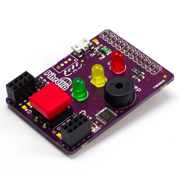
This is still one of my favorite accessories for my RPI due to the button, speaker and three LEDs, but also since I can hot swap jump wires without risk of shorting out the unit like when you’re using the direct GPIO on the RPI.
I have a great new setup for travel for my Raspberry Pi that has the newest 7in touchscreen and protective case, which opens on the back. Could I install my Pibrella with the constricted opening and the GPIO wires still powering the enhanced touchscreen card?
Knowing the GPIO setup
The Pibrella requires 26 of the pins to function and installation asks you to place the unit to the 1st pin. It has a mini USB connector for power, but can run off of the GPIO. The challenge is that the new 7inch touchscreen ALSO is powered by the RPI GPIO, connecting to pin 2, (5V) and 6, (Ground.)
When a competing configuration is found for GPIO, its important to inspect the GPIO map and see what is available:
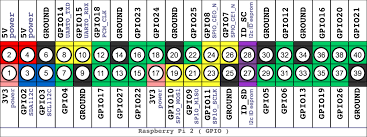
Now using the above map, you’ll notice that pins 1, 2 and 3 are all power. The Pibrella ONLY needs one 5V power source, which means that installing it from the first pin may be best practice, but it’s not required. OK, so that means we can still use Pin 2 for the touchscreen. Now, if we move down the Pibrella one, that leaves 6 rows of pins free at the other end. The 6 pin, which is the second necessary pin for the touch screen to ground it, can be shifted to the 39 pin, which is another ground pin!
I then moved the GPIO pins for the touchscreen and installed the Pibrella to the RPI 3. It was a tight fit, but it did install:
Test the Installation
The next thing was to test it all. Each of the GPIO connected match to the GPIO attached. These will have to all be tested to see if there are any mismatches between the board and the RPI. The Pibrella library that is installed is just functions that have been written to tell what pins correspond to what commands.
So I run a small test script:
import pibrella

import time

pibrella.light.red.on()

time.sleep(2)

pibrella.alarm.on()

pibrella.light.red.off()
This script is to turn on the red light for 2 seconds, ring an alarm and then shut off the red light.
What happened? The amber light lit on and then off. No alarm- yep, may have my monitor working and power to the pibrella, but as suspected, the GPIO orientation is off for each of the LEDs, alarm and I expect, the GPIO connections on the board.
Now I could give up my pibrella….or the touchscreen, but what if I’m just plain stubborn and want both?
So the files I need to work with are in the distribution packages for Pibrella. I had to go to /usr/local/lib/python2.7
Now you may be wondering why this was in the Python 2.7 instead of the 3.4 distribution… RPI 3 still has the 2.7 python set as default. If you don’t change this, then this is where you go. I prefer RPI 3 and write my code per Python 3 standards, but I’m not surprised the Pibrella library installed here.
Inside this directory, under the dist-packages is the Pibrella directory and it’s just a matter of .py, (python) files. There is one called pins.py that I had to update to reflect the changes I made to my match my installation. Now, we can fun the red light script and it actually lights up the correct LED.
It appears the alarm and button are set up in a different set of code, so now I need to just locate the other python scripts for the alarm and such and get that corrected.
That doesn’t mean I can’t get motors and other devices working from the new setup….
Oh Joy!!