Adding GPIO Pins to the Raspberry Pi Zero
Although the Raspberry Pi 3 is now available, many people are still interested in it’s cheaper, smaller version, the Raspberry Pi Zero. This version isn’t just smaller, it also requires a Wi-Fi dongle for internet access, (one of the new, great features on the 3 Model!) and one of my main reasons for not recommending it to newbies to the Raspberry Pi, (RPI) world, is that it doesn’t come with the GPIO pins pre-soldered.
GPIO, The In and Out to the World
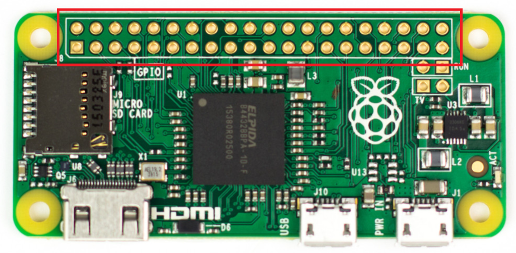
GPIO, which stands for General Purpose Input and Output is an excellent feature on this single board computer, allowing an RPI to connect easily with sensors, motors and other external components. The original RPI came with a 26 pin GPIO setup, but since the Module B, it’s been a standard 40 pin GPIO that offers a myriad of project and hardware possibilities.
Now those that are seasoned RPI geeks will simply say to wrap wires around the appropriate GPIO connector or with jumper wires, just stick the connector through the hole-
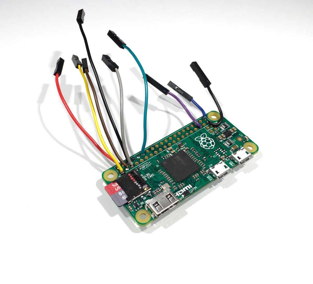
Those that introduce RPI to those new to single board computers know that the quickest way to suffer a short out to one is by performing breadboard and other experiments that utilize the GPIO and we see the wrapping of wires and leaving more chance for wires for power, grounding and control to touch a penchant for human error. These errors leave us asking students to be prepared with a backup image of the software on hand to address the most common victim of a shorted out unit.
Now I could go into the dangers of GPIO, ampage current with a recommendation that all newbies start with an Ardruino or discuss the importance of transistors, but eliminating some of the risk by having the GPIO pin connectors makes sense.
The Ardruino Vs. RPI Discussion
Ardruinos are better at GPIO ampage handling, but they shouldn’t be confused with a single board computer and are limited in their application. The RPI and Arduino are both capable of sinking 50 ma through their GPIO pins, the difference being where you to acually sink 50ma, the RPI may very well be damaged, but the arduino will survive and doesn’t have an Operating System and software that may be seriously impacted.
Due to this, for those that may be intermediates, I recommend if you’re going to get the Raspberry Pi Zero, consider soldering the GPIO pins for it. It’s not difficult and there are a lot of videos that can teach you how to solder effectively.
Soldering GPIO Pins on the Zero
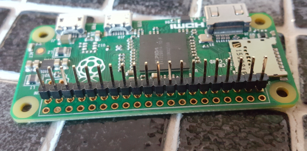
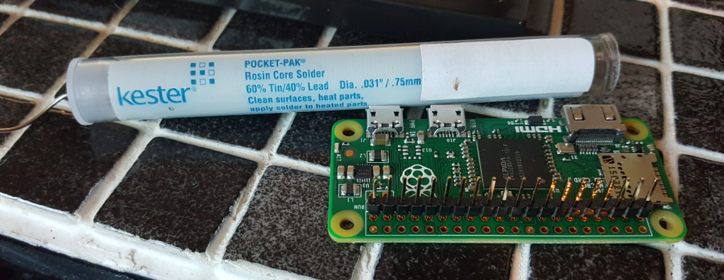
A 60 watt 110V soldering gun with a couple of different soldering tips is all you need to do the work with just about any RPI project. Purchase the right kind of solder for the project you’re taking on. Note I have a picture of the solder I’m using below. Pins can be purchased from Radio Shack, MicroCenter and other “geek stores” or you can steal them from kits that can be purchased online, like this cobbler kit. The pins can be “broken” into the correct count to fit in the holes to be soldered and you’ll be soldering from the back side of the unit.
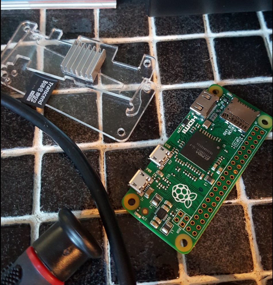
If the unit is in a case, please remove the case and ensure you remove any cables, micro SDCards, etc. that could get in the way or be in danger of harm by the soldering gun before you begin.
Set up your work area and I keep a piece of thick cardboard around to clean off any remnants of solder from my solder gun to keep it clean as I work. Add the correct number of pins and if you don’t have a single set of 40 pin addition you can add, work with one line at a time.
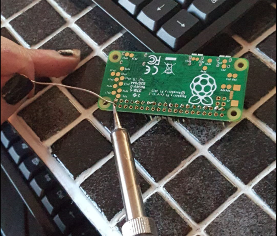
Once the first line of pins are added, turn the unit over and brace it so that the pins are straight. You don’t want them “leaning”, otherwise the pins could be soldered crooked and you could have challenges attaching units like a PiHat or other components that have configured GPIO attachments. I used the corner of my keyboard, as it was the right height and balanced it out nicely while I did the work. Make sure to use the right solder,- you can see what I used in the picture below:
Solder across the first line, taking care not to touch the actual Pi Zero with the soldering iron and once done with the first line, add the second line and solder it into place in the same way as you did the first:
Once finished, let it cool and check the connections. Are the pins tight and are they straight. If there is some angle to the pins, you can use the soldering iron to *carefully* loosen the solder and straighten them out some, but it’s better to be cautious and check it as you go to begin with.
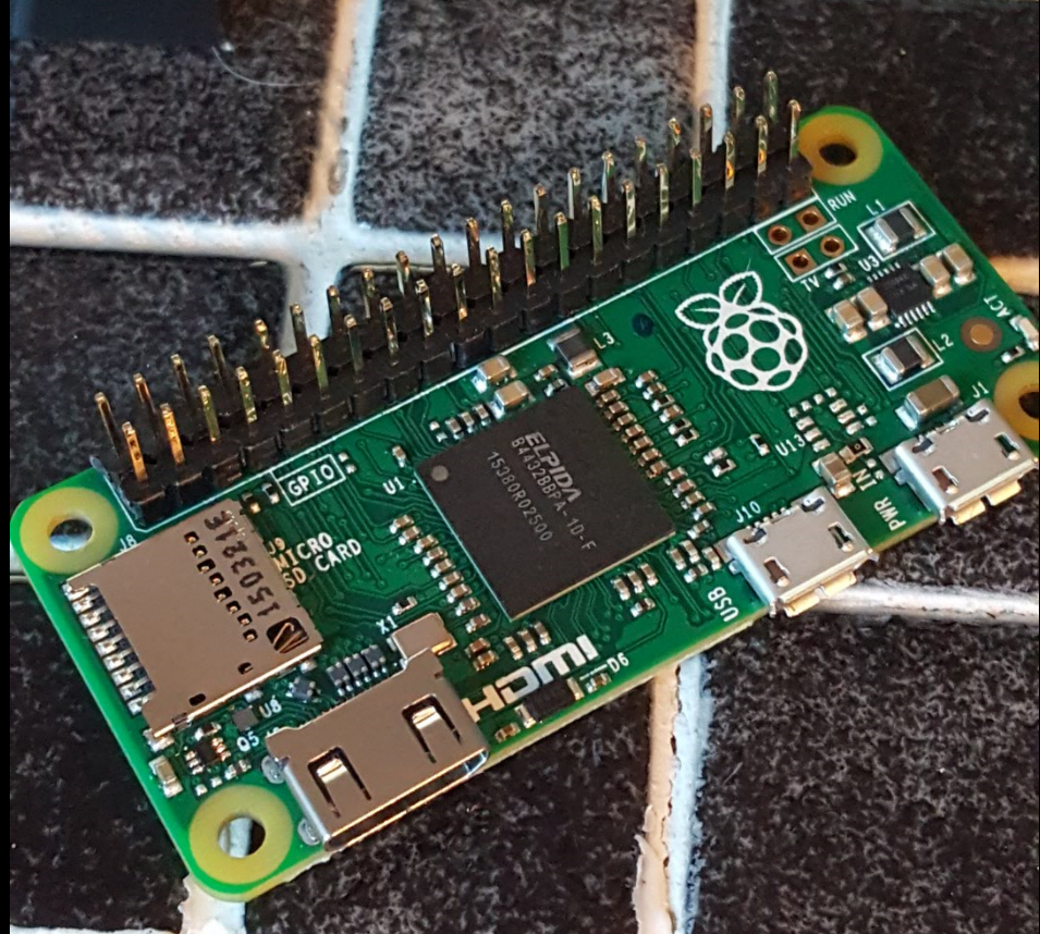
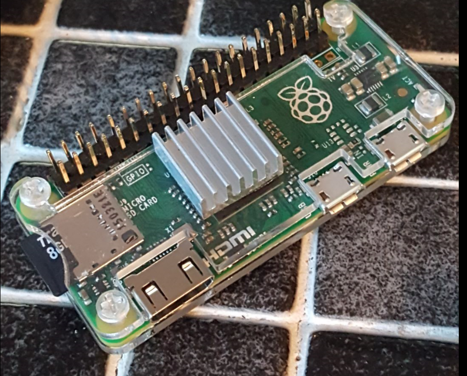
Once it’s cooled and you’re satisfied with the pin placement, plug back in the Micro SDCard and if you had a case, put the RPI zero back into it. That’s all there is to it! You’re ready to create all kinds of fun projects with your RPI Zero and not worry so much about those pesky GPIO wires being exposed! Oh, yeah, still make a backup of your image using Win32 Image Writer….PLEASE!! 🙂